What is an ohmmeter? What does it do? Information about its history and working principle. Information about ohmmeter design, usage and features.
Source: pixabay.com
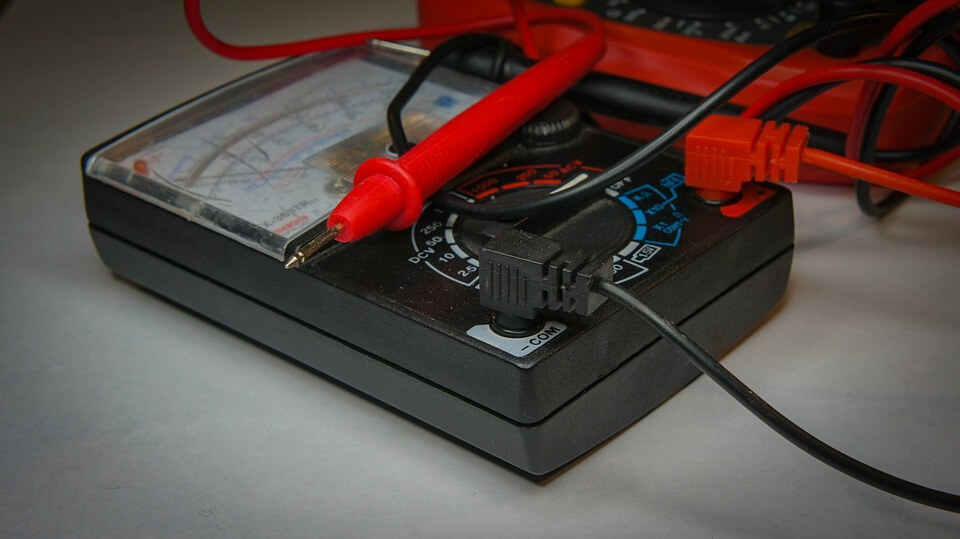
An ohmmeter is an electronic instrument used to measure the electrical resistance of a circuit or component. It works by applying a small voltage to the circuit or component and measuring the resulting current flow. Ohmmeters typically have a calibrated scale that shows the resistance value in ohms, although some digital ohmmeters may display the value numerically.
Ohmmeters are commonly used in electronics, electrical engineering, and physics for measuring the resistance of resistors, conductors, and other electrical components. They can help diagnose problems in circuits and ensure that components are functioning properly.
History of Ohmmeter
The concept of measuring electrical resistance was first introduced by Georg Simon Ohm, a German physicist, in 1827. Ohm’s Law, which describes the relationship between voltage, current, and resistance, provided the theoretical foundation for measuring electrical resistance.
The first practical ohmmeter was developed by Arthur William Siemens in the mid-19th century. Siemens’ design used a Wheatstone bridge circuit to measure the resistance of a component. This type of ohmmeter required the use of a separate power source, such as a battery, to provide the necessary voltage.
In the early 20th century, vacuum tube technology allowed for the development of more compact and portable ohmmeters. These early ohmmeters used a vacuum tube oscillator to generate the test voltage and a vacuum tube detector to measure the resulting current flow. These instruments were relatively bulky and expensive, however, and were primarily used in industrial and laboratory settings.
The development of solid-state electronics in the 1950s and 1960s led to the development of smaller and more affordable ohmmeters. Today, ohmmeters are commonly found in a variety of settings, from home electronics repair to industrial maintenance and testing. Digital ohmmeters are now the most common type of ohmmeter, providing quick and accurate measurements with little setup required.
What is Ohmmeter Working Principle?
The working principle of an ohmmeter is based on Ohm’s Law, which states that the current flowing through a conductor is directly proportional to the voltage applied across it, and inversely proportional to the resistance of the conductor. An ohmmeter works by applying a small known voltage across the circuit or component being tested and measuring the resulting current flow.
Ohmmeters typically have two terminals, one for connecting to the positive side of the voltage source, and another for connecting to the negative side of the voltage source. When the ohmmeter is connected to a circuit or component, a small voltage is applied across it, causing a small current to flow. The ohmmeter then measures this current and uses it to calculate the resistance of the circuit or component being tested.
Most ohmmeters use an internal battery or power source to generate the test voltage, and they may also include a built-in circuit to protect against damage from accidental overloading or reverse polarity connections. Ohmmeters may have analog or digital displays that show the resistance value in ohms, and they may include additional features such as auto-ranging or auto-calibration to make testing easier and more accurate.
Design evolution
The design of ohmmeters has evolved significantly over time, from early analog models to modern digital devices. Some of the key design changes and advancements include:
- Use of Wheatstone Bridge: The first practical ohmmeters used a Wheatstone bridge circuit to measure resistance. This required a separate power source to provide the necessary voltage.
- Vacuum Tube Technology: Early 20th-century ohmmeters used vacuum tubes to generate the test voltage and measure the resulting current flow. These instruments were relatively bulky and expensive.
- Solid-State Electronics: The development of solid-state electronics in the 1950s and 1960s led to the development of smaller and more affordable ohmmeters.
- Analog vs. Digital Display: Early ohmmeters typically had analog displays, which used a needle and dial to show the resistance value. Modern ohmmeters, however, almost exclusively use digital displays, which provide faster and more accurate readings.
- Auto-Ranging and Auto-Calibration: Some modern ohmmeters include auto-ranging and auto-calibration features, which make testing easier and more accurate.
- Portable and Handheld Design: Many modern ohmmeters are designed to be portable and handheld, allowing technicians and hobbyists to take them on the go.
Overall, the design evolution of ohmmeters has focused on making them smaller, more accurate, and easier to use. Today, ohmmeters are a common tool used in electronics, electrical engineering, and physics for measuring the resistance of a circuit or component.
